Autodesk Inventor Dynamic Simulation Tutorial using IN-Motion

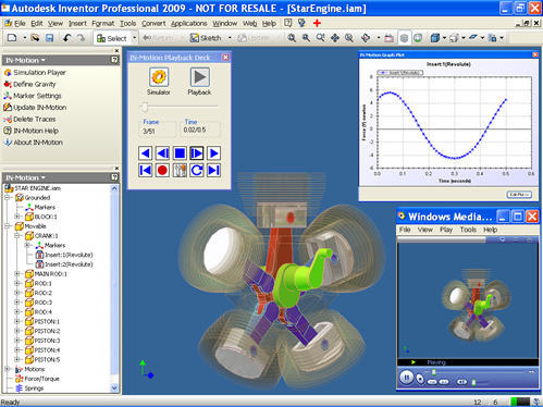
IN-Motion is a Motion and Dynamic Simulation Addin for Autodesk Inventor. Autodesk has certified IN-Motion as a compatible addin for Inventor 2009 and 2010 versions. In this tutorial, I shall explain in brief What is Dynamic Simulation using a simple example of 2 bodies. gravityText.iam has two parts namely housing (grounded part) and bob (pendulum). We define a Mate constraint between the cylindrical sufraces of these two parts. The mate created has 2 degrees of freedom (DOF). One is relative rotation between the two parts about their common axis and relative translation about their common axis. In Kinematics, this constraint is referred to as a Cylindrical joint / pair. Now that we have our assembly ready, we go to “IN-Motion” by clicking on “Environments” ribbon tab and then “IN-Motion” as shown in the figure below. (Inventor 2009, go to Applications >> IN-Motion )

IN-Motion loads up and converts all the Inventor constraints into corresponding Kinematic joints or pairs. In this case, Mate:1 constraint is converted to a cylindrical joint. We then define the “Gravity” acting on the assembly. From the IN-Motion tab, click on “Define Gravity” and enter the value of Gravity in Y direction = “-10” m/s^2. This will make the gravity act in the downward direction with respect to the below figure.

Now, we will look briefly at what we mean by Dynamic Simulation. We can draw “free body diagram” (FBD) of pendulum bob and derive the equations of motion for it. Since only gravity is acting on it., the forces acting on it is shown in the figure below. “F” corresponds to the resultant force acting on pendulum bob. “Fr” is the reaction force between the cylindrical surfaces of both the parts and “Fj” is force acting along the axis of the joint (joint force). Their values are calculated as shown in the figure below.

Click on the “Simulation Player” button in the top panel. A dialog / form appears. Change the end-time to 0.2 seconds and click on simulate button. IN-Motion now performs mathematical analysis and shows the messages as shown in the figure below. Click on the “Playback Deck” button and you can play the animation and notice that at the end of simulation, the bob comes down due to the action of gravity, which is evident from the equations of motion.

Now, we can determine the value of reaction force by performing Dynamic Simulation using IN-Motion. Right click on Mate:1(Cylindrical) and goto “Force /Torque Graph” context menu item. A graph plot appears and upon selecting “Force” and “Magintude”, the following graph appears.

You can observe that the numerical value of Force(N) v/s Time(s) almost remains constaint (but for minor variations due to numerical methods of computation). The value can be approximated to 4.678 N and we had got same value Fr from our Mathematical Calculation (Equations of Motion).

Now, we can define the Joint Force. Right click on Mate:1(Cylindrical) node and select “Define Force”. A dialog/ form appears.

Enter the value as “-4.0” N and simulate the assembly. You would observe that the pendulum still moves down, but the resultant force acting on it has been reduced and hence its displacement at the end of simualtion is less than that under free fall. We can also test the simulation for Force = “-5.0” N. This time, the pendulum moves upwards slowly. Lets do a final check by putting the value of Force = “-4.678” N.

If you simulate the assembly now, the pendulum bob does not move at all. This is the force thats same as Fj and hence it balances the force due to gravity and hence the pendulum is in Equilibrium.

This is how IN-Motion can be used to determine characteristics of Multi body systems and then we can define appropriate forces/torques or motion to see its affect on the system.

I had recorded a screencast of the above tutorial and its embedded below. For a high clarity video, check out AR-CAD website.

Hope to bring more such tutorials in future. For some people in Dynamic Simulation domain, tutorials of this kind may be very trivial, but majority of beginners could find simple tutorials like these useful. Please comment back if there is any confusion or suggestions.

Regards,

Rajeev Lochan

IN-Screenshot Free Addin for Autodesk Inventor

This post is for all Autodesk Inventor Users. How many times have you felt the need to take a screenshot of your Inventor file (assembly, part, drawing etc) and send it across to people who do not have Inventor or even upload the image online. You would have to follow one of the following two options

Option A: File > Save As> Save Copy As> and then select .jpg or .png as extension and save the file.

Option B: Use “Print Screen” key on your keyboard, go to MS Paint or other image editing software, paste the copied image and then save it.

At AR-CAD, we have developed a simple addin for Autodesk Inventor which lets you take screenshot or capture the current view of Inventor and save it as a jpg / png / gif or bmp image. And the best part about this addin is that its for FREE !!!. The addin developed is pretty simple and we just wanted to help Inventor users. We have developed the addin using Visual C#. Below images show an overview of IN-Screenshot usage in Inventor 2009 and Inventor 2010 (which has a Ribbon User Interface). To know more details and download IN-Screenshot addin, check out AR-CAD website.

It presently works on Inventor 2009 and 2010 versions and should also be able work on 2011, when it would be released. We have tested it to work on both 32 and 64 bit OS of Windows XP, Windows Vista and Windows 7.

You are free to try the addin and let us know your valuable feedback.

Disclaimer: Some days ago, I had come across a blog post pointing to ADN Addin of the month being awarded to a similar Inventor addin which saves the active view as an image. I had developed IN-Screenshot atleast an year ago and have no link with the other addin.

IN-Motion Released for Autodesk Inventor 2010

We have released IN-Motion for Autodesk Inventor 2010. IN-Motion is an affordable Motion and Dynamic Simulator for Autodesk Inventor. We had launched IN-Motion for 2009 version of Inventor earlier this year. Autodesk has certified IN-Motion to work with Inventor 2009 and 2010. We are also developing for 2011 version and would be available soon after Autodesk launches its product line for 2011 versions. For a detailed info on IN-Motion, check out IN-Motion 2009 blog entry. Download IN-Motion with 30 days free trial and once you are satisfied with it, you can buy a license for lifetime at just US$ 200.

A screenshot of IN-Motion running on Autodesk Inventor 2010 is below.

Please keep checking this blog for more updates and tutorials on IN-Motion and also Dynamic Simulation using Autodesk Inventor. If you have any query, please email to the following

Aik-Siong Koh (askoh@askoh.com) and Rajeev Lochan (rajeev@ar-cad.com)

Happy IN-Motioning :)

IN-Motion Launched for Autodesk Inventor 2009

Update: IN-Motion Released and Certified for Autodesk Inventor 2010.

Yes !! Finally we made it. After the extensive development of IN-Motion, we have launched it for Autodesk Inventor 2009. View Full Press Release. Download IN-Motion with 30 free trials

IN-Motion is an inexpensive Motion and Dynamic Simulation Addin for Autodesk Inventor. It has been certified by Autodesk to work with Autodesk Inventor 2009 version. We are in the process of developing IN-Motion for Autodesk Inventor 2010 and it should be released soonIN-Motion Released and Certified for Autodesk Inventor 2010 .

Check out the video below to get an overview of IN-Motion.

The Main Features of IN-Motion are:

IN-Motion is packed with all the above mentioned features and is available for download with 30 free trials. Once you are satisfied with our Addin, you can buy a lifetime license for just US$ 200.

If you are an Autodesk Inventor user and wanted to learn Dynamic Simulation, we have free online video tutorials at http://www.ar-cad.com/in-motion/tutorials/index.html

Please keep checking this blog for more updates and tutorials on IN-Motion and also Dynamic Simulation using Autodesk Inventor. If you have any query, please email to the following

Aik-Siong Koh (askoh@askoh.com) and Rajeev Lochan (rajeev@ar-cad.com)

Happy IN-Motioning 🙂

Update: IN-Motion Released and Certified for Autodesk Inventor 2010.

Free Autodesk Inventor Assembly Files

Update: IN-Motion, a Motion and Dynamic Simulation Addin for Autodesk Inventor has been launched by us.

Update: Video tutorials on usage of IN-Motion for Dynamic Simulation of Autodesk Inventor Assemblies.

Today, I stumbled upon a website which publishes textbooks, predominantly on CAD. While browsing through it, I figured out that they have a set of free Inventor assemblies, that can be downloaded. They can be found on this page on CADCIM. Scroll Down to section Inventor Files. A set of tutorials in pdf can also be found at the following URLs.

http://www.cadcim.com/Students_Project/basic_projects.htm
http://www.cadcim.com/Students_Project/intermediate.htm
http://www.cadcim.com/Students_Project/advance_projects.htm

Apart from CADCIM, there are other places where you can download Inventor Assembly and Part files for free. Check out

Update: Free Inventor Assembly files (used for Motion and Dynamic Simulation)

I shall try to update this blog post whenever I find more resources about free Autodesk Inventor parts or assemblies.

Minimize forms along with Parent Application or Form in C#

How to minimize forms that belong to a particular application, when the parent application (In my case Autodesk Inventor) is minimized ? When you create software or addins, you would want the forms/dialogs to be minimized and not floating around when parent application is minimized.

For that we need to deal with hWnd of parent application. “hWnd” stands for Window Handle, which is the API call to the window(parent application). Since we come across this too often in Inventor customization to make addins, I have created a Class and a couple of methods for better clarity. Before I go into details, lets see what are the different types of Forms/Dialogs you would deal while developing Windows based software.

1)Modal Forms or Dialog Box

Modal Form

The modal forms are used when you want the user to enter some values and unless the form/dialog is closed, he/she cannot interact with other controls in the application. All the MessageBox’s are of modal types. The image on the left is also an example of Modal forms. Here, the user has to enter/select details of Graph plots in our addin IN-Motion.


2. Modeless Form

The modeless forms are used when user can enter values into the form and also can interact with other controls in application, even when the form is not minimized. The image on the left is the Simulation playback deck in IN-Motion.


Coming back to our problem of minimizing forms with parent application, below is the code. If the user minimizes Inventor application(parent form), its child forms are also minimized.
[sourcecode language=’c#’]
//
//Declare and set..here m_inventorApplication is the application
//MainFrameHWND returns its handle.
//WindowsWrapperForForm is a Class, defined at the bottom
WindowsWrapperForForm m_windowsWrapperForForm = new
WindowsWrapperForForm((IntPtr)m_inventorApplication.MainFrameHWND);

//Declare and set a form .. ModalCmdDlg is our modal form
ModalCmdDlg m_modalCmdDlg = new ModalCmdDlg();

//Declare and set a form .. ModelessCmdDlg is our modeless form
ModelessCmdDlg m_modelessCmdDlg = new ModelessCmdDlg();

//Show Modal form
ShowModalForm(m_modalCmdDlg);

//Show Modeless form
ShowModelessForm(m_modelessCmdDlg);

//Methods
private void ShowModalForm(Form _modalCmdDlg)
{
_modalCmdDlg.Activate();
_modalCmdDlg.ShowInTaskbar = false;
//ShowDialog is used..for Modal forms
_modalCmdDlg.ShowDialog(m_windowsWrapperForForm);
}

private void ShowModelessForm(Form _modelessCmdDlg)
{
_modelessCmdDlg.Activate();
_modelessCmdDlg.ShowInTaskbar = false;
//Show is used..for Modeless forms
_modelessCmdDlg.Show(m_windowsWrapperForForm);
}

//Below is the code for Class WindowsWrapperForForm
//****************Class***************

class WindowsWrapperForForm : System.Windows.Forms.IWin32Window

{
private IntPtr m_hwnd;
public WindowsWrapperForForm(IntPtr handle)
{
m_hwnd = handle;
}
#region IWin32Window Members
public IntPtr Handle
{
get { return m_hwnd; }
}
#endregion
}
//****************EndClass*******************

[/sourcecode]

Opensource C# Graph Plot Library – ZedGraph

Update: Check out Zedgraph C# Graph Plot Example Application , I have an example ZedGraph Application (with sourcecode) to draw Line Plot, Bar Graph and Pie Chart.

Update 2: Check out ZedGraph C# Graph Data Export to CSV Using a Custom Context Menu , It has code to make a custom context menu item and also export the graph plot data as CSV.

ZedGraph C# Graph Library

I was searching for an opensource(hence free) Graph plotting library in C# (or VB.NET), so that it could be used in our IN-Motion addin for Autodesk Inventor. After some googling, I found 2 suitable open source libraries namely ZedGraph and NPlot. When both websites(read wiki) were compared, I found ZedGraph recently updated and also had great documentation to take off immediately. I readily downloaded the latest version of ZedGraph dll from its SourceForge project and followed the instructions on ZedGraph wiki.

Within no time, I was ready with ZedGraphTest example, whose screenshot is above. It is so simple that, without even exploring, I could accomplish basic graph plotting. Some of the plus points I see in ZedGraph are:

  • Not much tweaking of source-code is required for basic tasks.
  • All the plot elements (line, curve, panel, axes, plot-markers etc) can be set different colors. Even gradients can be set to have crazy as well as good looking Graphs
  • Different types of graphs (line,bar,pie etc) are possible with ease.
  • Using left click on the plot panel, the graph can be zoomed
  • Middle button can be used to pan the plot
  • Upon right click over the plot, a context menu appears which, out of the box has a lot of useful features such as saving the image, toggle the on-hover highligthing etc
The code for my ZedGraphTest is below. I have changed only CreateGraph() method, and the remaining code is same as in the example.
[sourcecode language=’c#’]
private void CreateGraph(ZedGraphControl zgc)
{
GraphPane myPane = zgc.GraphPane;

// Set the titles and axis labels
myPane.Title.Text = “ZedGraph Test”;
myPane.XAxis.Title.Text = “theta (angle)”;
myPane.YAxis.Title.Text = “Sin (theta)”;

// Make up some data points from the Sine function
PointPairList _list1 = new PointPairList();
for (double x = 0; x <= 360; x += 10) { double y = Math.Sin(x * Math.PI / 180.0); _list1.Add(x, y); } // Generate a blue curve with Plus symbols, LineItem _myCurve1 = myPane.AddCurve("Sin (theta)", _list1, Color.Blue,SymbolType.Plus); // Fill the pane background with a color gradient myPane.Fill = new Fill(Color.White, Color.FromArgb(220, 220, 255), 45F); //Make the MajorGrids of Axes visible myPane.XAxis.MajorGrid.IsVisible = true; myPane.YAxis.MajorGrid.IsVisible = true; // Calculate the Axis Scale Ranges zgc.AxisChange(); } [/sourcecode] So far, this library has been a boon to me as I dont have to reinvent the wheel again. Thanks a ton to ZedGraph guys 🙂

Free Autodesk Inventor Video Tutorial

Update: IN-Motion, a Motion and Dynamic Simulation Addin for Autodesk Inventor has been launched by us.

Update: Video tutorials on usage of IN-Motion for Dynamic Simulation of Autodesk Inventor Assemblies.

Free Autodesk Inventor Video Tutorial

Check out the free screencast on Autodesk Inventor, titled “Adding 3D with Autodesk Inventor” by Lynn Allen, Autodesk Technical Evangelist. She explains how Inventor is the best choice for AutoCAD users, which definitely helps AutoCAD users to make a transition to Inventor. I am pretty much impressed with the screencast as I could learn a lot from it. Though the Inventor version using which this screencast was created is old (compared to Inventor 2008 I am using), the knowledge transfer was pretty much effective. After watching this video, I could learn a lot of functionalities and features that Inventor has and most often which are under-used. Thanks Lynn for such a wonderful screencast.

IN-Motion: Motion Simulation Addin for Autodesk Inventor

Update: IN-Motion, a Motion and Dynamic Simulation Addin for Autodesk Inventor has been launched by us. Check out the below video for an Overview

Update: Video tutorials on usage of IN-Motion for Dynamic Simulation of Autodesk Inventor Assemblies.

For the past few months, along with my mentor (Aik-Siong Koh), I have been busy developing Motion Simulation addin for Autodesk Inventor. We have named it IN-Motion. Once we are done with the development, it would be available for Autodesk Inventor users, in the form of an addin. Upon installing IN-Motion, they will be able to simulate an assembly both kinematically and dynamically. The following screencasts show the progress we have achieved so far in this regard and very soon we will be launching IN-Motion.

1) Basic tutorial on getting started with IN-Motion. We start with a blank Inventor assembly and place components and apply constraint. Then we start IN-Motion, set rotation to a Insert Constraint (Revolute Joint) and then simulate the mechanism/assembly. Watch high resolution video at AR-CAD.


2) Tutorial on simulating a four-bar mechanism. This assembly has 2 grounded parts and 3 movable parts, with 4 Insert Constraints. IN-Motion allows us to give rotation to one of the Insert Constraints and then the simulation can be made to see the behavior of the imposed motion. Watch high resolution video at AR-CAD.


3) Tutorial on simulating an Elliptical Trammel. This assembly has 4 components. IN-Motion deals with Planar and Insert Constraints in this case and the simulation takes place for an imposed Rotation on one of the insert constraints. Watch high resolution video at AR-CAD.


4) Tutorial on simulating an Engine. We start with the engine assembly that gets shipped along with Autodesk Inventor. Right now, we are not dealing with the sub-assembly(Piston.iam) parts and constraints. We are considering the sub-assembly as a block/part. Upon user feedback, we may actually extend upon the sub-assembly parts. This is mainly because, a lot of processing takes place in our Motion Solver and the sub-assembly parts(if non-trivial) add up to the CPU load. Watch high resolution video at AR-CAD.


5) Tutorial on Dynamic Simulation of a pendulum in Autodesk Inventor, using IN-Motion. We take the pendulum from Tutorial 1 and instead of giving a rotation, we set the value of Gravitational force for the assembly. IN-Motion then passes the gravity to our Motion solver and the dynamic simulation of the assembly takes place. This example is the simplest form of dynamic simulation and complex assemblies can also be simulated for dynamics. We are working on getting velocity, acceleration and force data at any point in the assembly, in the form of a graph. Watch high resolution video at AR-CAD.

I am an Autodesk Authorised Developer

Update: IN-Motion, a Motion and Dynamic Simulation Addin for Autodesk Inventor has been launched by us.

Update: Video tutorials on usage of IN-Motion for Dynamic Simulation of Autodesk Inventor Assemblies.

Its been quite a long time since I last blogged. Some of the updates at my end

Autodesk Developer Network Logo

I have become an Autodesk Developer Network (ADN) member.


Secondly, I attended Autodesk Dev Days programme at Bangalore on November 12,2008. I could meetup with Autodesk guys and also Deelip Menezes of Sycode fame. I was lucky to be invited along with Deelip to dinner with Autodesk guys(picture below)


Third and most important update is the progress on IN-Motion. IN-Motion is the Motion Simulation addin we are developing for Autodesk Inventor. I am going to post screencasts on the progress of IN-Motion we have achieved so far and hoping to launch IN-Motion as soon as possible.