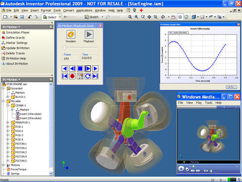
Autodesk Inventor Dynamic Simulation Tutorial using IN-Motion

IN-Motion is a Motion and Dynamic Simulation Addin for Autodesk Inventor. Autodesk has certified IN-Motion as a compatible addin for Inventor 2009 and 2010 versions. In this tutorial, I shall explain in brief What is Dynamic Simulation using a simple example of 2 bodies. gravityText.iam has two parts namely housing (grounded part) and bob (pendulum). We define a Mate constraint between the cylindrical sufraces of these two parts. The mate created has 2 degrees of freedom (DOF). One is relative rotation between the two parts about their common axis and relative translation about their common axis. In Kinematics, this constraint is referred to as a Cylindrical joint / pair. Now that we have our assembly ready, we go to “IN-Motion” by clicking on “Environments” ribbon tab and then “IN-Motion” as shown in the figure below. (Inventor 2009, go to Applications >> IN-Motion )

IN-Motion loads up and converts all the Inventor constraints into corresponding Kinematic joints or pairs. In this case, Mate:1 constraint is converted to a cylindrical joint. We then define the “Gravity” acting on the assembly. From the IN-Motion tab, click on “Define Gravity” and enter the value of Gravity in Y direction = “-10” m/s^2. This will make the gravity act in the downward direction with respect to the below figure.

Now, we will look briefly at what we mean by Dynamic Simulation. We can draw “free body diagram” (FBD) of pendulum bob and derive the equations of motion for it. Since only gravity is acting on it., the forces acting on it is shown in the figure below. “F” corresponds to the resultant force acting on pendulum bob. “Fr” is the reaction force between the cylindrical surfaces of both the parts and “Fj” is force acting along the axis of the joint (joint force). Their values are calculated as shown in the figure below.

Click on the “Simulation Player” button in the top panel. A dialog / form appears. Change the end-time to 0.2 seconds and click on simulate button. IN-Motion now performs mathematical analysis and shows the messages as shown in the figure below. Click on the “Playback Deck” button and you can play the animation and notice that at the end of simulation, the bob comes down due to the action of gravity, which is evident from the equations of motion.

Now, we can determine the value of reaction force by performing Dynamic Simulation using IN-Motion. Right click on Mate:1(Cylindrical) and goto “Force /Torque Graph” context menu item. A graph plot appears and upon selecting “Force” and “Magintude”, the following graph appears.

You can observe that the numerical value of Force(N) v/s Time(s) almost remains constaint (but for minor variations due to numerical methods of computation). The value can be approximated to 4.678 N and we had got same value Fr from our Mathematical Calculation (Equations of Motion).

Now, we can define the Joint Force. Right click on Mate:1(Cylindrical) node and select “Define Force”. A dialog/ form appears.

Enter the value as “-4.0” N and simulate the assembly. You would observe that the pendulum still moves down, but the resultant force acting on it has been reduced and hence its displacement at the end of simualtion is less than that under free fall. We can also test the simulation for Force = “-5.0” N. This time, the pendulum moves upwards slowly. Lets do a final check by putting the value of Force = “-4.678” N.

If you simulate the assembly now, the pendulum bob does not move at all. This is the force thats same as Fj and hence it balances the force due to gravity and hence the pendulum is in Equilibrium.

This is how IN-Motion can be used to determine characteristics of Multi body systems and then we can define appropriate forces/torques or motion to see its affect on the system.

I had recorded a screencast of the above tutorial and its embedded below. For a high clarity video, check out AR-CAD website.

Hope to bring more such tutorials in future. For some people in Dynamic Simulation domain, tutorials of this kind may be very trivial, but majority of beginners could find simple tutorials like these useful. Please comment back if there is any confusion or suggestions.

Regards,

Rajeev Lochan

IN-Screenshot Free Addin for Autodesk Inventor

This post is for all Autodesk Inventor Users. How many times have you felt the need to take a screenshot of your Inventor file (assembly, part, drawing etc) and send it across to people who do not have Inventor or even upload the image online. You would have to follow one of the following two options

Option A: File > Save As> Save Copy As> and then select .jpg or .png as extension and save the file.

Option B: Use “Print Screen” key on your keyboard, go to MS Paint or other image editing software, paste the copied image and then save it.

At AR-CAD, we have developed a simple addin for Autodesk Inventor which lets you take screenshot or capture the current view of Inventor and save it as a jpg / png / gif or bmp image. And the best part about this addin is that its for FREE !!!. The addin developed is pretty simple and we just wanted to help Inventor users. We have developed the addin using Visual C#. Below images show an overview of IN-Screenshot usage in Inventor 2009 and Inventor 2010 (which has a Ribbon User Interface). To know more details and download IN-Screenshot addin, check out AR-CAD website.

It presently works on Inventor 2009 and 2010 versions and should also be able work on 2011, when it would be released. We have tested it to work on both 32 and 64 bit OS of Windows XP, Windows Vista and Windows 7.

You are free to try the addin and let us know your valuable feedback.

Disclaimer: Some days ago, I had come across a blog post pointing to ADN Addin of the month being awarded to a similar Inventor addin which saves the active view as an image. I had developed IN-Screenshot atleast an year ago and have no link with the other addin.

IN-Motion Released for Autodesk Inventor 2010

We have released IN-Motion for Autodesk Inventor 2010. IN-Motion is an affordable Motion and Dynamic Simulator for Autodesk Inventor. We had launched IN-Motion for 2009 version of Inventor earlier this year. Autodesk has certified IN-Motion to work with Inventor 2009 and 2010. We are also developing for 2011 version and would be available soon after Autodesk launches its product line for 2011 versions. For a detailed info on IN-Motion, check out IN-Motion 2009 blog entry. Download IN-Motion with 30 days free trial and once you are satisfied with it, you can buy a license for lifetime at just US$ 200.

A screenshot of IN-Motion running on Autodesk Inventor 2010 is below.

Please keep checking this blog for more updates and tutorials on IN-Motion and also Dynamic Simulation using Autodesk Inventor. If you have any query, please email to the following

Aik-Siong Koh (askoh@askoh.com) and Rajeev Lochan (rajeev@ar-cad.com)

Happy IN-Motioning :)

IN-Motion Launched for Autodesk Inventor 2009

Update: IN-Motion Released and Certified for Autodesk Inventor 2010.

Yes !! Finally we made it. After the extensive development of IN-Motion, we have launched it for Autodesk Inventor 2009. View Full Press Release. Download IN-Motion with 30 free trials

IN-Motion is an inexpensive Motion and Dynamic Simulation Addin for Autodesk Inventor. It has been certified by Autodesk to work with Autodesk Inventor 2009 version. We are in the process of developing IN-Motion for Autodesk Inventor 2010 and it should be released soonIN-Motion Released and Certified for Autodesk Inventor 2010 .

Check out the video below to get an overview of IN-Motion.

The Main Features of IN-Motion are:

IN-Motion is packed with all the above mentioned features and is available for download with 30 free trials. Once you are satisfied with our Addin, you can buy a lifetime license for just US$ 200.

If you are an Autodesk Inventor user and wanted to learn Dynamic Simulation, we have free online video tutorials at http://www.ar-cad.com/in-motion/tutorials/index.html

Please keep checking this blog for more updates and tutorials on IN-Motion and also Dynamic Simulation using Autodesk Inventor. If you have any query, please email to the following

Aik-Siong Koh (askoh@askoh.com) and Rajeev Lochan (rajeev@ar-cad.com)

Happy IN-Motioning 🙂

Update: IN-Motion Released and Certified for Autodesk Inventor 2010.

IN-Motion: Motion Simulation Addin for Autodesk Inventor

Update: IN-Motion, a Motion and Dynamic Simulation Addin for Autodesk Inventor has been launched by us. Check out the below video for an Overview

Update: Video tutorials on usage of IN-Motion for Dynamic Simulation of Autodesk Inventor Assemblies.

For the past few months, along with my mentor (Aik-Siong Koh), I have been busy developing Motion Simulation addin for Autodesk Inventor. We have named it IN-Motion. Once we are done with the development, it would be available for Autodesk Inventor users, in the form of an addin. Upon installing IN-Motion, they will be able to simulate an assembly both kinematically and dynamically. The following screencasts show the progress we have achieved so far in this regard and very soon we will be launching IN-Motion.

1) Basic tutorial on getting started with IN-Motion. We start with a blank Inventor assembly and place components and apply constraint. Then we start IN-Motion, set rotation to a Insert Constraint (Revolute Joint) and then simulate the mechanism/assembly. Watch high resolution video at AR-CAD.


2) Tutorial on simulating a four-bar mechanism. This assembly has 2 grounded parts and 3 movable parts, with 4 Insert Constraints. IN-Motion allows us to give rotation to one of the Insert Constraints and then the simulation can be made to see the behavior of the imposed motion. Watch high resolution video at AR-CAD.


3) Tutorial on simulating an Elliptical Trammel. This assembly has 4 components. IN-Motion deals with Planar and Insert Constraints in this case and the simulation takes place for an imposed Rotation on one of the insert constraints. Watch high resolution video at AR-CAD.


4) Tutorial on simulating an Engine. We start with the engine assembly that gets shipped along with Autodesk Inventor. Right now, we are not dealing with the sub-assembly(Piston.iam) parts and constraints. We are considering the sub-assembly as a block/part. Upon user feedback, we may actually extend upon the sub-assembly parts. This is mainly because, a lot of processing takes place in our Motion Solver and the sub-assembly parts(if non-trivial) add up to the CPU load. Watch high resolution video at AR-CAD.


5) Tutorial on Dynamic Simulation of a pendulum in Autodesk Inventor, using IN-Motion. We take the pendulum from Tutorial 1 and instead of giving a rotation, we set the value of Gravitational force for the assembly. IN-Motion then passes the gravity to our Motion solver and the dynamic simulation of the assembly takes place. This example is the simplest form of dynamic simulation and complex assemblies can also be simulated for dynamics. We are working on getting velocity, acceleration and force data at any point in the assembly, in the form of a graph. Watch high resolution video at AR-CAD.

Customize Autodesk Inventor API using C# – Part 3

In continuation to my previous post on Customizing Inventor using C#, I go a step further and interact with an opened Assembly through API. I have ported the code from VBA to C# for the example explained in Introduction to Inventor API and VBA (Visual Basic for Applications). The attached document is from Autodesk University of 2003.

Start a new C# Windows Application project in Visual Studio 2005, as done in previous tutorial. Design the form as shown in the image to the left. Double clicking on Hide / Show will take you to Form1.cs in the Code Viewer window and add/append the following code into it. Please note that I have changed the Names/Identifiers of form elements to txtSearchName , cmdShow, cmdHide as explained in the above tutorial document.

In this example, when you hit ‘F5’ or Debug, a windows form appears as shown. Type a part name in the Search Field and hit “Hide”. If any part(s) exist in the opened assembly with that name, it/they would be made invisible. If its hidden and you hit on “Show”, the part would be made visible. In our case, we have made Piston part invisible in the engine assembly that ships with Inventor as an example assembly. Save the application by File> Save All in Visual Studio.

You can also use this Windows Application by executing the .exe file that is produced, when you debug/build your application. In my case, its at My DocumentsVisual Studio 2005ProjectsWindowsApplication1WindowsApplication1binDebugWindowsApplication1.exe . Double clicking on the exe file would also popup the Form that was developed.

Form1.cs code

[sourcecode language=’c#’]
using System;
using System.Collections.Generic;
using System.ComponentModel;
using System.Data;
using System.Drawing;
using System.Text;
using System.Windows.Forms;

namespace WindowsApplication1
{
public partial class Form1 : Form
{
//Instantiate a variable with Inventor.Application object.
//It should have a scope throughout this Class
private Inventor.Application oApp=(Inventor.Application)System.Runtime.
InteropServices.Marshal.GetActiveObject(“Inventor.Application”);

//Declare oAsmDoc to have a scope within this Class
private Inventor.AssemblyDocument oAsmDoc;
public Form1()
{
InitializeComponent();

//Check that a document is open
if (oApp.Documents.Count == 0)
{
MessageBox.Show(“An Assembly must be active”);

}
//Check that an assembly document is active
if (oApp.ActiveDocument.DocumentType !=
Inventor.DocumentTypeEnum.kAssemblyDocumentObject)
{
MessageBox.Show(“As Assembly document must be active”);

}
//First Type Cast ActiveDocument into AssemblyDocument
//Set a reference to the active document
oAsmDoc = (Inventor.AssemblyDocument) oApp.ActiveDocument;
}

private void cmdHide_Click(object sender, EventArgs e)
{
//Call the function that traverses the assembly
// and sets the visibility.
SetVisibility(oAsmDoc.ComponentDefinition.Occurrences,
txtSearchName.Text, false);

//Update the View.
oApp.ActiveView.Update();
}

private void cmdShow_Click(object sender, EventArgs e)
{
//Call the function that traverses the assembly
// and sets the visibility.
SetVisibility(oAsmDoc.ComponentDefinition.Occurrences,
txtSearchName.Text, true);

//Update the View.
oApp.ActiveView.Update();
}

private static void SetVisibility
(Inventor.ComponentOccurrences Occurences, string SearchName,
bool VisibilityOn)
{
//Iterate through each of the occurences
//in the collection provided.
foreach (Inventor.ComponentOccurrence oOccurence in Occurences)
{//Check to see if the occurence name matches the search name
//The strings are converted to lower case
// to remove context sensitivity.
if(oOccurence.Name.ToLower().Contains(SearchName.ToLower()))
{//Check to see if the visibility is different than the specified
if (oOccurence.Visible != VisibilityOn)
{//Set the Visibility of the occurence.
oOccurence.Visible = VisibilityOn;
}
}
}
}
}
}
[/sourcecode]

Customize Autodesk Inventor API using C# – Part 2


Watch High Resolution video on AR-CAD

I hope you have gone through my previous posts on Inventor API a) Introduction to Autodesk Inventor API and Customization and b) Customize Autodesk Inventor using C#. It is also assumed that you have gone through DevTV: Introduction to Inventor Programming Video, which is on Inventor Customization page. In the above video, we connect to Inventor API from Visual C# (Visual Studio 2005). I have just replaced the VB.NET code that was used in DevTV tutorial with the corresponding C# code. You can see the comparison below. Please note how GetObject in VB.NET is replaced by a much more lengthier code. If the above youtube video is not very clear, watch it on AR-CAD.

VB.NET Code
[sourcecode language=’vb’]
Dim oApp As Inventor.Application
oApp = GetObject( , “Inventor.Application”)
MsgBox(“Number of open docs = ” & oApp.Documents.Count)
[/sourcecode]

Visual C# Code
[sourcecode language=’c#’]
Inventor.Application oApp;
//The below initialization is on a single line
oApp =
(Inventor.Application)System.Runtime.InteropServices.Marshall.
GetActiveObject(“Inventor.Application”);

int number_int = oApp.Documents.Count;
string number_string = Convert.ToString(number_int);

MessageBox.Show (“Number of open docs =” + number_string);
[/sourcecode]

Introduction to Autodesk Inventor API and Customization

Update: IN-Motion, a Motion and Dynamic Simulation Addin for Autodesk Inventor has been launched by us.

Update: Video tutorials on usage of IN-Motion for Dynamic Simulation of Autodesk Inventor Assemblies.

Autodesk Inventor Logo For those in CAD (Computer Aided Design) field, Autodesk would have been a very common company they would have come across. One of the most famous CAD software, AutoCAD belongs to their stable. Autodesk Inventor is somewhat an extension of AutoCAD, specific for Manufacturing section and deals mainly with 3D CAD, solid modeling of parts and then building assemblies out of them, Rapid Prototyping and many more advanced features. Inventor has been a great success in this field and it is evident from the fact that there are more than 800,000 official licensed users of Inventor across the world.

One of the strong points for the success is the fact that Autodesk has opened its API (Application Program Interface) to developers who can extend the base product to fit into their requirements. This is called Customization of the CAD package. Inventor also has its API exposed to developers through COM (Component Object Model) interface using which developers can customize the base installation of Inventor to tailor made needs such as automating a certain process or developing addins/ addons/ plugins which do specific task.

For those, who want to get started with Inventor API customization using their SDK (Software Development Kit), the following steps can be followed.

  1. Introduction to Inventor API and VBA (Visual Basic for Applications). The attached document is from Autodesk University of 2003. Though it may seem to be old, its a very good starting point and the code works even in latest versions of Inventor.
  2. You may also consider going through the 3 part series of Focused VBA for Inventor, which is a part of AUGI Training Program (2007) : Part 1, Part 2 and Part 3.
  3. Visit Inventor Customization page and get more insight, by watching 1 hour video on Basics of Inventor API and developing addins for Inventor (DevTV: Introduction to Inventor Programming )
  4. Decide upon which .NET technology you would be comfortable in developing Addins and Standalone applications (Either of VB.NET, VC++ or Visual C#)
  5. Browse through Inventor Customization forum to get more insights, code examples and also problems faced by other developers and also an active Autodesk support team which answers those queries
  6. If you happen to progress well, consider joining Autodesk Developers Network (ADN) and also attend AUGI Training Programs (ATP)
  7. Also you can keep a track on my Blog as I would be trying to pen down my learning, developing full fledged Addins for Inventor and also other major CAD software.

Glad am back to CAD World.. Crossroads of my Career

Update: IN-Motion, a Motion and Dynamic Simulation Addin for Autodesk Inventor has been launched by us.

Crossroads in Career Its been quite some time since I blogged. I was pretty much occupied with the Confusion I had in my mind, as I had hit a Cross-Roads of my career. After quitting my job at HeroHonda R&D, I teamed up with my mentor, Aik-Siong Koh in US and we started off with AR-CAD in April 2007. Since he is an expert at CAD (Motion Simulation) and he had used Smalltalk to develop freeCAD, I also had to learn Smalltalk to help him in further development. Our initial plan was to develop Motion Add-ons/Add-ins or Plug-ins for various CAD software such as Autodesk Inventor, SolidWorks, Rhino CAD and others. Somehow in the due course, we thought of exploring Web 2.0 using Seaside, which is a web framework built on Smalltalk. The idea was that I could learn Smalltalk and also explore Web 2.0 as we had plans for integration of Web and CAD.

We started developing Caartz using Seaside. It took us a long time to get it out. During this period, I learnt Smalltalk, Seaside, OOP, Basic Linux Setup and Usage, various Web related configurations such as Apache, load-balancing etc. When Caartz was launched, it was just a lot of things we had learnt and we had no plans to make money out of it. Since I had gathered experience in Web domain, I completely forgot that I had to return to CAD to make Motion Add-ons.

Then I helped a friend to develop a couple of websites and took a Web Developer Job in a Bangalore based Services Startup. Though the work there involved me in whole life cycle of a project and was very challenging, I thought I was missing something there. Being a Mechanical Engineer from a reputed Engineering College with a lot of interest in CAD, I had a feeling that I was not doing what I was supposed to do. After a couple of months in that Web Startup, I quit it and again I have teamed up with my mentor in US to develop CAD Add-ons.

This time, we are very serious about our path we are going to follow to become a very known name in Motion Simulation Domain. We have completely revamped AR-CAD website as the first step. My mentor already has Motion Simulation code in Smalltalk. I am learning VBA and .NET C# to develop an Add-in which talks to both Autodesk Inventor COM API and our Smalltalk code. As of today, I am able to make simple VBA Add-ons for Inventor and hopefully within next 6 months, we would be ready to sell our Motion Add-ons for Inventor. Once it is done, we would then develop Motion Add-ons for other CAD software.

Jist of my post is that I had come across a Crossroads a year ago and chose a road which took me to Web 2.0 domain. Somewhere down the line, I realized that I wasn’t enjoying it and came back to the crossroads and now I have chosen the road which takes me into CAD world and I am glad that I am finding it interesting and challenging.